

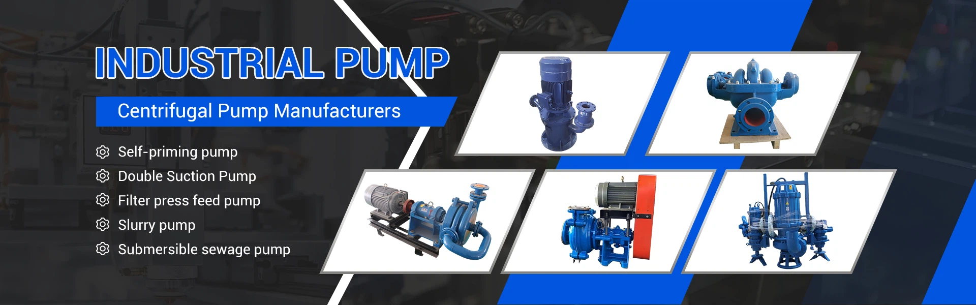
The so-called vertical slurry pump, when running, part of the pump needs to be immersed in the liquid, and the motor part is located above the liquid surface. The best-selling vertical slurry pumps in China are SP series and ZJL series.
The SP series submersible slurry pump is a foreign imported technology; the ZJL series submersible slurry pump is independently developed in China.
The structures of the two series of submersible slurry pumps are very similar, and they look the same at first glance. How to distinguish the two series of vertical slurry pumps?
1. Look at the number of pump body bolts. The SP series submersible slurry pump has 3 bolts, while the ZJL series submersible slurry pump has 4 bolts.
2. Structural features: The SP series slurry pump has a semi-open impeller, while the ZJL series has a closed impeller.
Full range of vertical slurry pump models:
SP submersible slurry pump models include: 40PV-SP(R), 65QV-SP(R), 100RV-SP(R), 150SV-SP(R), 200SV-SP(R), 250TV-SP(R), and 300TV-SP(R).
Model meaning: Taking 65QV-SP(R) as an example, 65 indicates that the pump outlet diameter is 65mm, QV bracket form, SP series code, and R indicates rubber lining.
ZJL vertical slurry pump models include: 40ZJL-21, 40ZJL-25, 40ZJL-35, 50ZJL-20, 50ZJL-35,
50ZJL-40, 65ZJL-30, 80ZJL-36, 100ZJL-34, 150ZJL-35.
Model meaning: Taking 65ZJL-30 as an example, 65 means the pump outlet diameter is 65mm, ZJ means slurry pump, L means vertical, and 30 means the impeller diameter is 30cm.
To learn more about slurry pump model parameters and selection tips, please call us for consultation!
4. Working principle and common models of slurry pumps
According to the working principle, slurry pumps are impeller pumps. Impeller pumps drive the liquid to rotate at high speed through the working impeller, transferring mechanical energy to the liquid, thereby achieving the purpose of conveying liquid.
Impeller pumps are divided into centrifugal pumps, vortex pumps, axial flow pumps and mixed flow pumps according to the different characteristics of the impeller and flow channel structure. Slurry pumps belong to centrifugal pumps in terms of working principle.
Working principle of slurry pumps:
The pump casing of the slurry pump is stationary, and the impeller rotates at high speed driven by the motor. The impeller generates centrifugal force through high-speed rotation. The centrifugal force acts on the liquid filled in the tank, and the liquid is thrown from the center of the impeller to the surroundings and thrown into the pump casing, so that the liquid obtains kinetic energy and potential energy.
Because the volume of the pump casing outside the impeller continues to increase, the medium at the outlet of the slurry pump has greater energy, so that the liquid is transported to a certain height and distance through the drainage pipe.
When the liquid is thrown out to the surroundings under the action of centrifugal force, a low-pressure zone is formed at the inlet of the impeller, and the external liquid is immersed in the impeller through the inlet pipe due to the action of atmospheric pressure.
Common models of slurry pumps:
M, AH, HH series new slurry pumps.
ZJ series new slurry pumps.
5. How to calculate the head and flow rate of slurry pumps
1. Head of slurry pumps
Head is the energy obtained by the slurry pump per unit weight of liquid. The calculation of slurry pump head can be roughly divided into three cases (as shown in the figure):
The first: h=D+S+hf1+hf2+h3+ Pd-Ps
The second: h= D-S+hf1+hf2+hf3+ Pd-Ps
The third: h= D+S+hf1+hf2+hf3+ Pd-Ps
D--discharge geometric height, m; value: higher than the center line of the pump inlet: positive; lower than the center line of the pump inlet: negative;
S--suction geometric height, m; value: higher than the center line of the pump inlet: negative; lower than the center line of the pump inlet: positive;
Pd, Ps--operating pressure in the container, m liquid column (gauge pressure); value: based on the positive and negative gauge pressure
Hf1--straight pipe resistance loss, m liquid column;
Hf2--pipe fitting resistance loss, m liquid column;
Hf3--inlet and outlet local resistance loss, m liquid column;
h--pump head, m liquid column.
2. Slurry pump flow
The determination of slurry pump flow mainly has the following three points:
1. The minimum, normal and maximum flow rates are given in the production process of slurry pumps, and the maximum flow rate should be considered.
2. Only the normal flow rate is given in the production process, and a certain margin should be considered.
For large-flow, low-lift slurry pumps with NS>100, the flow margin is 5%, for small-flow, high-lift pumps with NS<50, the flow margin is 10%, and for pumps with 50≤NS≤100, the flow margin is also 5%. For pumps with poor quality and poor operating conditions, the flow margin should be 10%.
3. The basic data only gives weight flow, which should be converted into volume flow.
6. Four ways to improve energy saving of slurry pumps
As we all know, slurry pumps are indispensable equipment in the mineral processing industry. Their main function is to provide power for pipeline transportation.
The slurry pumps are used in an unreasonable way or blindly, which leads to problems such as energy waste and excessive wear of the pumps. In fact, as long as we correctly and reasonably choose and use the slurry pump according to our own situation, we can use the slurry pump efficiently. The following is a brief explanation by the technical engineer of Dale Pump Industry Co., Ltd. on several ways to use the slurry pump reasonably:
1. Reasonably choose the lining material according to the type of ore
There are many types of lining materials for slurry pumps, such as high-chromium cast iron, high-chromium white cast iron and wear-resistant rubber. Faced with the choice of many materials, many merchants are hesitant. Choose high-chromium cast iron material, which has good wear resistance and is limited to the use of ore dressing plants containing coarse and sharp particles in the slurry; high-chromium white cast iron material has good wear resistance, but its toughness is poor and cannot withstand the rapid impact of large solid particles. Otherwise, it will cause the impeller surface material to fall off, and the cross section is prone to pits due to corrosion; wear-resistant rubber material has better wear resistance and corrosion resistance than metal materials, and has high elasticity, but it is only suitable for conveying fine-grained slurry without edges. Therefore, the selection of slurry pump linings needs to be reasonably selected according to the type of ore, so as to improve the utilization rate of the pump.
2. Select according to the actual flow and head required
When selecting a slurry pump, most users only pay attention to the flow selection of the pump and ignore the pump head selection. Some people even think that the higher the head, the safer it is, so the head of the selected slurry pump should be greater than the actual head requirement, resulting in a large waste of electricity. The selection of slurry pumps should be based on the actual head requirement to reduce the number of installed units and save electricity. In addition, it should be noted that when calculating the head, the loss head needs to be considered to avoid insufficient pump head and affect the pump irrigation and drainage efficiency.
3. The motor and slurry pump power must be reasonably matched
The unreasonable matching of the motor and slurry pump power is mainly reflected in the two aspects of "big cows pulling small plows, small cows pulling large plows", especially the first phenomenon is particularly common, the matching power is large, resulting in a large waste of electricity. The latter matching power is small, that is, "small cows pulling large plows", which will cause insufficient slurry supply of the slurry pump. If the motor is overloaded or cannot drive the pump, the safe and economical operation of the equipment cannot be guaranteed. The solution is to reasonably match the motor and the slurry pump power.
4. Scientific and reasonable installation of slurry pump
If conditions permit, when installing the slurry pump, try to reduce the use of elbows, or cancel the "three valves". The pipeline is best to be straight and short. Do not set the outlet pipe to an "anti-aircraft gun" style. You can use methods such as lying down and tilting to reduce losses. The diameter of the pipeline has a great influence on the loss head. It is best to use a water pipe with a diameter slightly larger than the slurry pump diameter, which can improve the transportation efficiency of the slurry pump.
The above four are introductions to the reasonable selection and use of slurry pumps. As long as the ore dressing plant uses these methods reasonably, it will definitely improve the production efficiency of its own ore dressing plant and achieve the goal of energy saving and high efficiency.


